Beneath the Surface
Real Thru-process Core Temperatures for Perfect Aluminium Slab Reheat
Aluminium Slab/Ingot Reheat Processing Control
In the hot working of aluminium stock, the initial cast slab is passed through continuous pusher furnaces to reheat and homogenise at temperatures up to typically 550 °C (1022 °F). The actual
set-point temperature and soak time employed in the process is obviously influenced by the stock characteristics including type of alloy and the physical dimensions of the slab, thickness, and overall thermal mass. Although modern furnaces incorporate sophisticated temperature control methods, often based on intelligent mathematical models, the success of the heat treat programs requires independent validation. The process engineer needs to understand how the furnace program characteristics, unique to each furnace (temperature and time) effect the temperature of the aluminium slab throughout the complete production heat treatment cycle (passage through the furnace) at different locations within the slab structure (length, width and depth). Other techniques used for product temperature measurement in process, including furnace contact thermocouples and IR temperature measurement (spot, scanner or camera) limit temperature to the surface slab and often are restricted to one face of the slab only. To achieve efficient hot rolling it is critical the correct slab drop out temperature is achieved through the entire slab core.
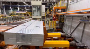
Fig 1: Test Al Slab with installed/encapsulated temperature monitoring system being loaded into the pusher furnace. Thru-furnace slab core temperature measurement is possible safely and efficiently, even live in real time, without use of trailing thermocouples.
Validation of Furnace Control Programs – Slab Temperature Profiling Challenge
To validate the performance of the heat treat process a temperature profile of the slab temperature at different locations within the slab through the heat treat furnace is needed.
To eliminate the inherent problems of the trailing thermocouple approach the alternative method of Thru-process temperature profiling is recommended. As its name suggests the measurement system (data logger) passes through the process attached to the test slab during normal production conditions, measuring the temperature of the test slab using short thermocouples at up to 20 critical points. The data logger is protected from the heat of the furnace by a highly efficient thermal barrier which keeps it at a safe operating temperature. As the monitoring system is self-contained within the test slab the system is free to travel safely through the furnace without any of the inherent challenges of long trailing thermocouples as part of the standard production cycle within a fully loaded furnace.
Thru-process Temperature profiling system design.
PhoenixTM Data logger Range
At the heart of the monitoring system is the data logger designed specifically for use in the hostile heat treat environment. Data loggers can be provided in a variety of configurations to suit the specific demands of the process being monitored. Models ranging from 6 to 20 channels can be provided with a variety of thermocouple options (types K, N, R, S, B) to suit measurement temperature and accuracy demands (AMS2750 & CQI-9).
Although thermally protected by the thermal barrier the operating temperature of the data logger during transfer through the furnace will increase up to the safe maximum operating conditions
(100 °C (212 °F) in evaporative water barrier). The data logger temperature change, which would normally affect the thermocouple reading, is automatically compensated for using an accurate internal temperature compensation feature protecting the measurement accuracy in process.
Built to cope with hostile industrial environments the IP67 logger is capable of managing even the most demanding processes where water spray quenching may be necessary.
An optional unique 2-way RF telemetry package offers live real time logger control and process monitoring. Slab core temperature readings recorded by the data logger, in-process, are transmitted directly from the furnace back to the monitoring PC via a network of RF repeater units.
Thermal Barrier Design
Heat treating a 30 tonne 600 mm / 24 inch thick aluminium slab requires significant heat to achieve homogeneity. Processes are typically therefore up to 20 hours at 500 °C / 932 °F and as such the thermal barrier used to protect the data logger needs to be very efficient but at the same time be compact enough to allow safe installation within the slab.
For such process the recommended thermal barrier design is based on a dual phased evaporation technology. The high temperature data logger operating safely at temperatures up to 110 °C / 230 °F is housed within the dry cavity of a water tank. Data logger sealing options within the thermal barrier are available including IP67 compression fittings, recommended if water spray quench steps are employed in process. During transfer through the furnace the water heats up to it’s boiling point at 100 °C / 212 °F and then maintains the temperature as water phase changes from liquid to gas (steam). The rate by which the water temperature in the tank rises is further controlled by an outer skin of microporous insulation which helps reduce rapid temperature changes and associated risk of distortion problems for the thermal barrier structure.
The exact thermal barrier protection is governed by the capacity of the water tank. When specifying the correct thermal barrier design often there is a fine balance between maximizing the size of the water tank and volume of water available to the outer dimensions of the thermal barrier suiting the size of the slab being monitored.
A feature of the pusher furnace design is that the slab is rotated at the entrance and exit of the furnace to maximize loading capacity. The rotation of the slab and therefore also thermal barrier could create problems with water loss and deterioration in thermal capacity. The water tank construction is designed therefore in a unique way to orientate water filler and steam exhaust pipes to minimise water loss during any rotation step.
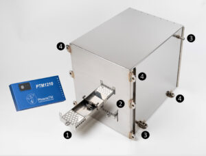
Fig 2: Aluminium slab thermal barrier showing (1 & 2) dual data logger tray within water tank and (3) filler and exhaust pipes and (4) slab mounting points.
Fitting the monitoring system to the test slab
Generally, a test slab is prepared by machining a portion out to accept the monitoring system with the thermal barrier often positioned centrally and, in a position, where it will not impede any equipment used to load / unload the slab.
The assembled monitoring system fitted within the slab cavity is covered with an external metal shield (Figure 3). The shield has two purposes to firstly protect the thermal barrier from high levels of heat transfer from high velocity hot air convection and maintain air flow patterns over the slab itself to maintain normal production heating conditions.
Fig 3: PhoenixTM System embedded in aluminium slab/Ingot – a stainless steel cover (not shown) is used to protect from high velocity air flow in furnace
Thermocouple Placement
Temperatures within the slab are measured from the tip of the mineral insulated thermocouple. To position the tip at the exact location / depth within the slab pilot holes need to be drilled in the slab. Depending on the type and diameter of thermocouple to be used, aluminium bushes may need to be used as guides. If a small diameter thermocouple is used, for example a 1.5mm 1/16 inch diameter mineral insulated type, then it would be impractical to drill a small hole say 300mm / 11.8 inches deep to the measuring point. In this case a large diameter hole can be drilled, and bushes used. It is essential that the thermocouples are firmly secured to the slab as they travel from the data logger to the measuring point. Often the thermocouples are channelled along groves in the slab surface so that the cables are confined within the slab eliminating snagging risks in the furnace, or on charging / discharging the equipment (See product insert image in Figure 4).
Handling the Data
The result of the thru-process monitoring step is the invaluable temperature profile graph (Figure 4). The profile graph represents a thermal fingerprint of what temperatures the aluminium slab achieved through the process at the selected locations over the slab footprint and at specified depths within its core. The profile data can be interrogated in detail to fully understand the heat treat operation at the critical product level and be used to control, optimize and validate the furnace operation. Such data is essential to accurately set-up and verify mathematical model predictions used to control the furnace operation and ensure that the process is run efficiently to save energy, improve productivity and reduce carbon emissions.
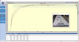
Fig 4: Temperature profile graph showing the temperature variations within the aluminium slab core over the entire heat treat process. Soak times at critical temperatures can be accurately calculated to ensure that drop out temperatures and rolling operations are performed correctly.
Conclusion
Thru-process product temperature profiling is an accurate and efficient method to measure aluminium slab internal core temperatures in pusher furnaces prior to hot rolling operations. Non-homogeneous temperature conditions can be prevented that would potentially cause variation in downstream processing and compromised final product quality, ultimately leading to energy wastage, higher costs, and rejections.