Decoding the Heat Treat DNA
Thru-process temperature monitoring and process validation
strategies (CQI-9) in the Automotive Heat Treatment industry
The Heat Treat Monitoring Goal
In any automotive heat treatment processes to achieve the physical material properties of the product it is essential that the heat treat application is performed in a controlled and repeatable fashion. This means that the product material experiences the required temperature, time and processing atmosphere to achieve the desired metallurgical transitions (internal micro-structure) to give the product the material properties to perform it’s intended function.
When tackling the need to understand how the heat treat process is performing it is possibly useful to split the task up into two, focusing on the furnace technology first, and then introduce the product into the mix.
If we consider the furnace performance we need to validate that the heat treat technology is capable of providing the desired accurate uniformity of heating over the working volume of the furnace for the desired soak time where the products are placed. This is best achieved by performing a temperature uniformity survey (TUS). The TUS is a key pyrometry requirement of the CQI-9 HTSA (AIAG) standard applied by many automotive OEMs and suppliers.
Traditionally temperature uniformity surveys (TUS) are performed using a field test instrument (chart recorder or static data logger) external to the furnace with thermocouples trailing into the furnace heating chamber. Although possible, this technique has many limitations, especially when applying to the ever increasingly automated semi or continuous operations discussed later in this article.
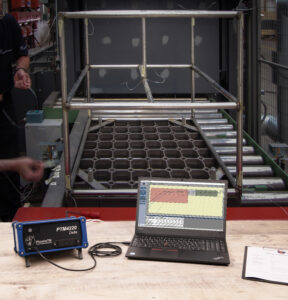
Fig 1. Typical TUS survey set-up for a static batch furnace. PhoenixTM PTM1-420 External data logger connected directly to a 9 point TUS
frame used to measures the temperature uniformity over the volumetric working volume of the furnace.
Thru-process Temperature Profiling – discover the Heat Treat DNA
In many respects although the TUS operation gives a level of confidence that the furnace technology is in specification when it comes to heat treatment it is important to understand that we need to focus on what is happening at the real core of the product from a temperature time perspective. Product temperature profiling, as its name suggests is the perfect technique. Thermocouples attached to the part or even embedded within the part give an accurate record of the product temperature at all points in the process referred to as a product temperature profile. Such information is helpful to determine process variations from critical factors such as part size, thermal mass, location within the product basket, furnace loading, transfer rate and changes to heat treat recipe.
Product temperature profiling, although possible by trailing thermocouples with an external data logger (Figure 1) for a simple batch furnace, realistically it is not an option for some modern heat treat operations. With the industry driving to fully automated manufacturing, furnace manufacturers are now offering the complete package with full robotic product loading; shuttle transfer systems and modular heat treat phases to either process complete product baskets or one piece operations.
The ‘Thru-process’ monitoring principle overcomes the problems of trailing thermocouples as the multi-channel data logger (Field test intrument) travels into and through the heat treat process protected by a thermal barrier (Figure 2). The short thermocouples are fixed to either the product or TUS frame. Temperature data is then transmitted either live to a monotoring PC running Profile or TUS analysis software, via a 2-way RF Telemetry link or dowloaded post run.
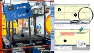
Fig 2. PhoenixTM ‘Thru-process’ monitoring system. The Thermal barrier (1) protects internal multi-channel data logger (2) (Field Test Instrument).
(3) Product Thermal Profile (4) Temperature Uniformity Survey (TUS) (5) Short nonexpendable mineral insulated thermocouples .
Although thru-process temperature monitoring in principle can be applied to most heat treat furnace operations, obvioulsy no one solution with suit all processes, as we know from the phrase “One size doesn’t fit all.” For this very reason unique thermal barrier designs are required taylored specifically to the demands of the application whether temperature, pressure, atmosphere or geometry as described in the folowing section.
Product Profiling and Temperature Surveys (TUS) in continuous heat treat furances
Thru-process product temperure profiling and or Surveying (TUS) of continuous furnace operations, unlike trailing thermocouples, can be performed accurately and safely as part of the conventional production flow allowing true heat treat conditions to be assessed. As shown in Figure 3 surveying of the furnace working zone can be achieved using the plane method. A frame attached to the thermal barrier positions the TUS thermocouples at desginated positions relative to the two dimensional working zone (furnace height and width) as defined in the pyrometery standard (CQI-9) during safe passage through the furnace (soak time).
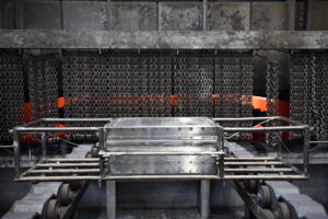
Fig 3. Temperature Uniformity Survey (TUS) of a continuous furnace using the plane method applying the PhoenixTM thru-process monitoring system.
Data logger travels protected in a thermal barrier mounted on the TUS frame performing a safe TUS at 4 points across the width, impossible by trailing
thermocouples.(photograph courtesy of Raba Axle, Györ, Hungary.)
Sealed Gas Carburizing and Oil Quench Monitoring
For traditional sealed gas carburising where product cooling is performed in an integral oil quench the historic limitation of ‘thru-process’ temperature profiling has been the need to bypass the oil quench and wash stations.
In such carburizing processes the oil quench rate is critical to both the metallurgical composition of the metal but also elimination of product distortion and quench cracks so the need for a monitoring solution has been significant. Regular monitoring of the quench is important as ageing of the oil results in decomposition, oxidation and contamination of the oil all degrading the heat transfer characteristics and quench efficiency.
To address the process challenges a unique barrier design has been developed that both protects the data logger in the furnace (typically 3 hours @ 925 °C / 1700 °F) but also protects during transfer through the oil quench (typically 15 mins) and final wash station.
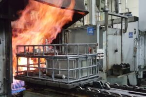
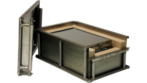
Fig 4. PhoenixTM Thru-process temperature profiling system monitoring the core temperature of automotive parts in a
traditional sealed gas carburizing furnace with integral oil quench. (4.1) System entering carburizing furnace in product basket
(4.2) Thermal barrier showing outer structural frame and sacrificial insulation blocks protecting inner sealed thermal barrier housing the data logger.
The key to the barrier design is the encasement of a sealed inner barrier (Figure 4) with its own thermal protection with blocks of high-grade sacrificial insulation contained in a robust outer structural frame. The innovative barrier offers complete protection to the data logger allowing product core temperature monitoring for the complete heat treat process under production conditions.
Low Pressure Gas Carburizing with High Pressure Quench (TUS)
In the current business environment, an attractive alternative to the traditional sealed gas carburizing application for both energy and environmental reasons is Low Pressure Carburizing (LPC). Following the vacuum carburizing process, the product is transferred to a sealed high-pressure gas quench chamber where the product is rapidly gas cooled using typically N2 or Helium at up to 20 bars. Such technology lends itself to automation with product baskets being transferred by shuttle drives, robot loading mechanisms from chamber to chamber in a semi-continuous fashion. The sequential processing with often stages being performed in self-contained sealed chambers can only be monitored by the thru-process approach where the system (Thermal barrier protected data logger) is self-contained within the product basket or TUS frame.
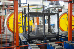
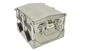
Fig 5: Thermal barrier being loaded into LPC batch furnace with TUS frame as part of temperature uniformity survey.
(5.1) Thermal barrier shown with independent Quench deflector providing protection during the High Pressure Gas Quench.
In such processes the technical challenge is twofold. The thermal barrier must be capable of protecting against not only heat during the carburizing phase but also very rapid pressure and temperature changes inflicted by the gas quench. To protect the thermal barrier in the LPC process with gas quench the barrier construction needs to be able to withstand constant temperature cycling and high gas pressures. The design and construction features include;
- Metal Work – 310 stainless steel employed to reduce distortion at high temperature combined with internal structural reinforcement.
- Insulation – Ultra-high temperature microporous insulation minimizes shrinkage problems.
- Rivets – Close pitched copper rivets reduce carbon pick up and maintain strength.
- Lid expansion plate – Reduces distortion during rapid temperature changes
- Catches – Heavy duty catches eliminating thread seizure issues
- Heat Sink – Internal heat sink to provide additional thermal protection to data logger
During the gas quench the barrier needs to be protected from Nitrogen N2(g) or Helium He(g) gas pressures up to 20 bar. Such pressures on the flat top of the barrier would create excessive stress to the metal work and internal insulation / data logger. To protect the barrier therefore a separate gas quench deflector is used. The tapered top plate deflects the gas way from the barrier. The unique design means the plate is supported on either four or six support legs. As it is not in contact with the barrier no force is applied directly to the barrier and the force is shared between the support legs.
In LPC technology further monitoring challenegs are faced by the development of one piece flow furnace designs. New designs incoroprate single piece or single product layer tray loading into multiple vertical heat treat chambers followed by auto loading into mobile high pressure quench chamber. Miniturization of each separate heat treat chamber obviously limits the space available to the monitoring system. The TS02-128 thermal barrier has been designed specifically for such processes utilizing the compact 6 channel “Sigma” data logger allowing reduction of the foot print of the system to fit the product tray and reduce thermal mass. With a height of only 128 mm / 5 inch and customized independent low height quench deflector the system is suitable for challenging low height furnace chambers and offer 1 hour protection at 800 °C / 1472 °F in a vacuum.
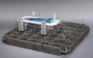
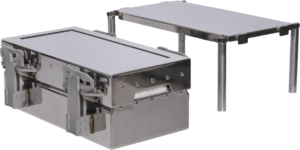
Fig 6: Low profile TUS system (TS02-128-1 thermal barrier six channel Sigma data logger) designed with TUS surveying individual one-piece flow heat treatment LPC furnace chambers.
(6.1) Thermal barrier shown with optional low profile gas quench deflector.
Rotary hearth furnce monitoring – Solution reheat of Aluminium Engine blocks.
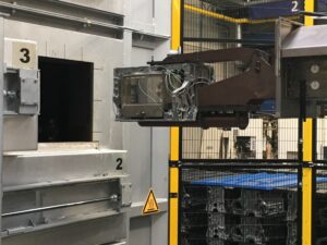
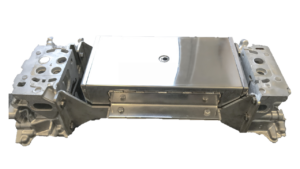
Fig 7: Robot loading of combined ‘thru-process’ system with engine block into BSN rotary T6 furnace.
The thermal barrier is designed with a combination of thermal insulation technology capable of fitting in the engine block cavity.
(7.1) Thermal barrier mounted within engine block assembly. (photos courtesy of BSN Thermprozesstechnik GmbH)
In modern rotary hearth furnaces such as that shown in figure 7 temperature profiling using trailing thermocouples is impossible as the cables would wind up in the furnace transfer mechanism. Due to the central robot loading and unloading and elimination of charging racks/baskets the use of a conventional thru-process system would also be a challenge. To eliminate the loading restrictions a unique thermal barrier small enough to fit inside the cavity of the engine block and allow automated loading of the complete combined monitoring system and product has been developed. To optimize the thermal performance of the thermal barrier with such tight size constraints a phased evaporation technology is employed. Thermal protection of the high temperature data logger is provided by an insulated water tank barrier design keeping the operating temperature of the data logger at a safe 100 °C / 212 °F or less. The system allowed BSN Thermoprozesstechnik GmbH in Germany to commission the furnace accurately and efficiently and thereby optimize settings to not only achieve product quality but ensure energy efficient, cost effective production.